STRUCTURAL DESIGN OF CABLE
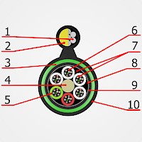
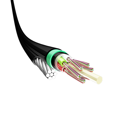
The bearing member is placed in parallel to the twisted conductor. The bearing member can consist of a steel rope or a dielectric-based strength member (fiberglass rod). Optical fibers are freely placed inside the tube and interstice is filled with a hydrophobic gel. Polymer tubes are SZ stranded around a central-strength member. Interstice between stranded tubes is filled with hydrophobic gel and covered with PET tape. The core is sheathed with polyethylene intermediate jacket. The cable is wrapped with laminated corrugated steel armor and the parallel bearing member is sheathed with high-density polyethylene jacket.

- Steel rope (T)/ steel wire (Ts)
- Glass rod (Td)
- Corrugated steel tape armor
- Central member
- PBT tube
- Optical fiber
- Hydrophobic gel
- PET tape
- Inner jacket
- Outer protective jacket
COLOR IDENTIFICATION OF FIBERS AND TUBES (IEC 60304)
Number of fibers | 2-24 | 26-48 | 50-72 | 74-96 | 98-144 |
The number of tubes (max.) | 6 | 6 | 6 | 8 | 12 |
Number of fibers in a tube (max) | 4 | 8 | 12 | 12 | 12 |
Temperature range during operation | -40 °C.....+60 ºC |
Temperature range during installation | -10 °C.....+50 ºC |
Temperature range during transportation and storage | -50 ºC......+50 ºC |
Minimum bend radius | 20xD |
Tensile strength (IEC 60794-1-2) | 1 ÷ 3.5 kN |
Crush strength (IEC 60794-1-2) | 3.0 kN/100 mm (min) |


